
Procedural terrain generation
With focus on hydraulic erosion
For my specialization i wanted to make a simulated terrain using compute shaders on the GPU using my groups game engine (TEMP engine). The erosion model used in this specialization is based of two papers [1] and [2].
5 - 7 Step process:
- Water incrementation.
- Flow simulation and computation of velocity field and water height changes.
- Soil flow simulation. (Optional)
- Simulation of hydraulic erosion.
- Transportation of suspended sediment.
- Thermal erosion. (Optional)
- Water evaporation
The reason why it says 5 to 7 steps, is because the thermal erosion is not necessary to get believable terrain but those 2 steps add alot to the terrains erosion models final product. But this page will not go through those steps.
1. Water incrementation:
Quite a simple step. I take in a position where new water should be added. I then in a compute shader make a radius around that point, and any indexes inside of that radius gets the added water amount.
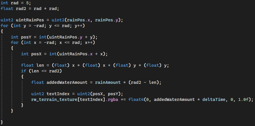
One thing to note, on the CPU side i have the option to switch between random positions on the terrain and a constant set position. If it is the latter then the added water acts like a constant water source.
2. Flow simulation:
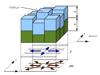
For the flow of water, I use a texture and map all the water outflow flux directions to the different channels of the texture (blue lines in the image on the side).
To break this whole step down, we can imagine that this step is the sum of 5 smaller steps.
- Calculate the outflow flux pipes.
- Calcluate K (K is a scaling factor aimed to avoid negative water height).
- Scale outflow flux values by a factor of K .
- Update water height in each grid cell.
- Calculate the velocity field using outflow flux values.
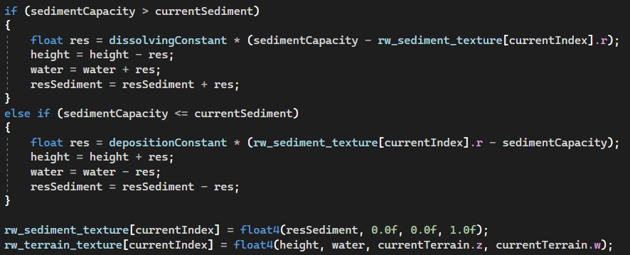
3. Simulation of hydraulic erosion:

The erosion is somewhat straightforward. We calculate a sediment capacity based on sediment capacity constant, the local tilt angle of current grid cell and the lenght of current grid cells velocity vector.

I then use the sedimentCapacity to see if the sediment should be deposited or dissolved. It will be deposited if the sedimentCapacity is lower than the current grid cells sediment, and it will disolve if the sedimentCapacity is higher than the current grid cells sediment.
4. Transportation of suspended sediment:
In this step we transport the suspended sediment acording to the semi-Lagrangian advection method.
The papers state that if the position that we get out of the calculation is out of bound from the terrains grid. Then you're supposed to interpolate between the four nearest neighbors and get the right position and use that.

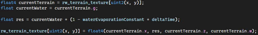
5. Water evaporation:
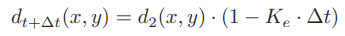
Like the first step this is also a very simple step, I follow the equation presented in the papers.
Final result
Resources:
[1] Fast Hydraulic and Thermal Erosion on the GPU
[2] Fast Hydraulic Erosion Simulation and Visualization on GPU